
H-Bridge DC Dual Motor Driver Motor-shield PWM DC 3 ~ 36V 15A (30A pulse)
Italy
Nexive: orders below 24,98 € shipping costs is 2,50 € - shipping times of 7 - 15 working days
Nexive: orders above 24,99 € shipping is FREE - shipping times of 7 - 15 working days
DHL: orders of less than euro 24,98 € shipping costs is 9,90 € - shipping times of 2 - 3 working days
DHL: orders between 24,99 € and 49,98 € shipping costs is 7,90 € - shipping times of 2 - 3 working days
DHL: orders between 49,99 € and 98,99 € shipping costs is 5,90 € - shipping times of 2 - 3 working days
DHL: orders above 99 € shipping is FREE - shipping times of 2 - 3 working days
Europe
DHL: fixed cost of euro 15,99 € for the whole European territory - shipping times of 2 - 3 working days
Poste Italiane Registered: 250 gr. max weight limit and the cost varies from 7,10 € to 12,70 € - shipping times of 2 - 4 weeks.
Rest of the World
DHL: fixed cost of 39,99 € for the rest of the world - shipping times of 2 - 3 working days
Poste Italiane Registered: 250 gr. max weight limit and the cost varies from 8,40 € to 16,50 € - shipping times of 2 - 4 weeks.
H-Bridge DC Dual Motor Driver Motor-shield PWM DC 3 ~ 36V 15A (30A pulse)
 Buying this product you will collect 20 points with our loyalty program. Your can convert 20 points in your account into a voucher for a future purchase.
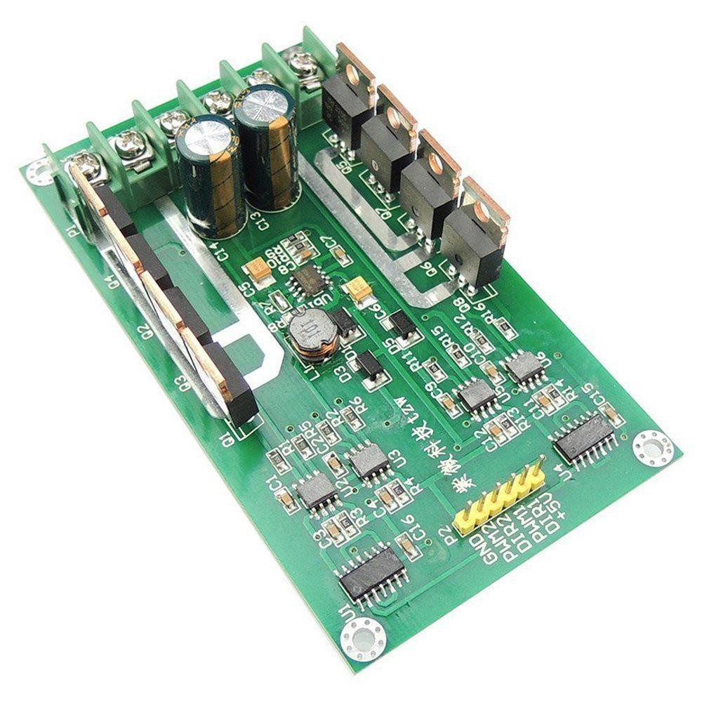
This shield allows you to control two different motors at the same time. The board has a very wide operating voltage range, which favors its versatility as it can be integrated into small and large robots. The board uses the PWM protocol for optimal compatibility with all types of microcontrollers (e.g. Arduino, Esp32 etc…). This module is equipped with N-channel Mosfets that combine excellent performance with very low current losses, this feature makes the card perfect for battery applications.
| Nominal voltage: | 3v-36v DC |
| Nominal current: | 15A |
| Peak current: | 30A |
| Max. Power without heatsink¹: | 1W per engine |
| PWM Max. Freq. : | 50KHz |
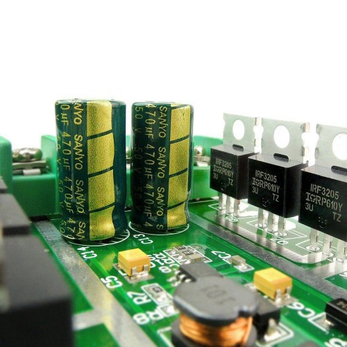
| N-Channel Mosfet: | RU6099R |
¹: The heatsinkless Mosfets with powers greater than ~ 1W exceed their maximum operating temperature (175 ° C), this increases the risk of breakage and significantly reduces the life of the component
The motor card has a maximum continuous rated current of 16 A. However, the maximum power that can be supplied by the card is strictly linked to the ability of the Mosfets (black IC with metal fin, positioned on the sides of the card) to dissipate the heat produced. Performance can certainly be improved by adding an isolated heatsink² (not included).
²: The board needs independent "heat sinks" (one for each mosfet) to reach the maximum declared power. Furthermore, care must be taken that the metal bodies of the individual Mosfets remain isolated from each other.
The value of ~ 1W has been calculated using the formula below (Fig. 1), however this value does not take into account the losses due to the inversion of state which increases the energy to be dissipated, so it is advisable not to exceed the power of 1W if the Mosfet is not equipped with a suitable heatsink.
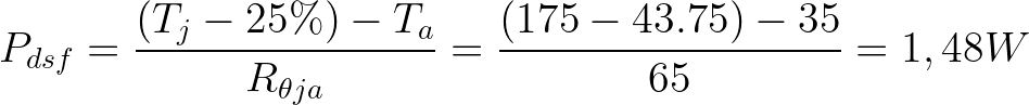 Fig.1
Fig.1
Legend:
Maximum power for Mosfet operation without danger of overheating
Maximum temperature of the silicon junction
Safety factor including other losses not considered in the function
Ambient temperature in ° C
Coefficient of thermal resistance between junction and environment
NB: This product can get hot enough to burn you a lot before the chip overheats. Be careful when handling this product and other related components.
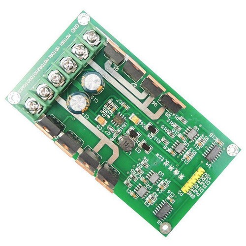
On the motor board we find at the two ends the connectors for the logic signals (Eg PWM1, DIR1 ...) and on the other side the power terminals (Eg MOT1, MOT2 ...). To connect the motor card to a generic controller just follow the image below (Fig. 1), these are the minimum connections to make the scheda with two motors, if you want to control only one motor you can leave the unaffected pins unconnected (therefore PWM2, DIR2).
Note that if the controller has a low consumption it can be directly powered by the motor board by connecting the pin "+ 5V" to the input (typically "Vin") of the controller. However, make sure that the controller does not receive other power sources such as from a PC connected via a USB cable or a battery. check in the controller power supply specifications that the voltage is compatible (5V) and the current does not exceed the limit of 500mA.
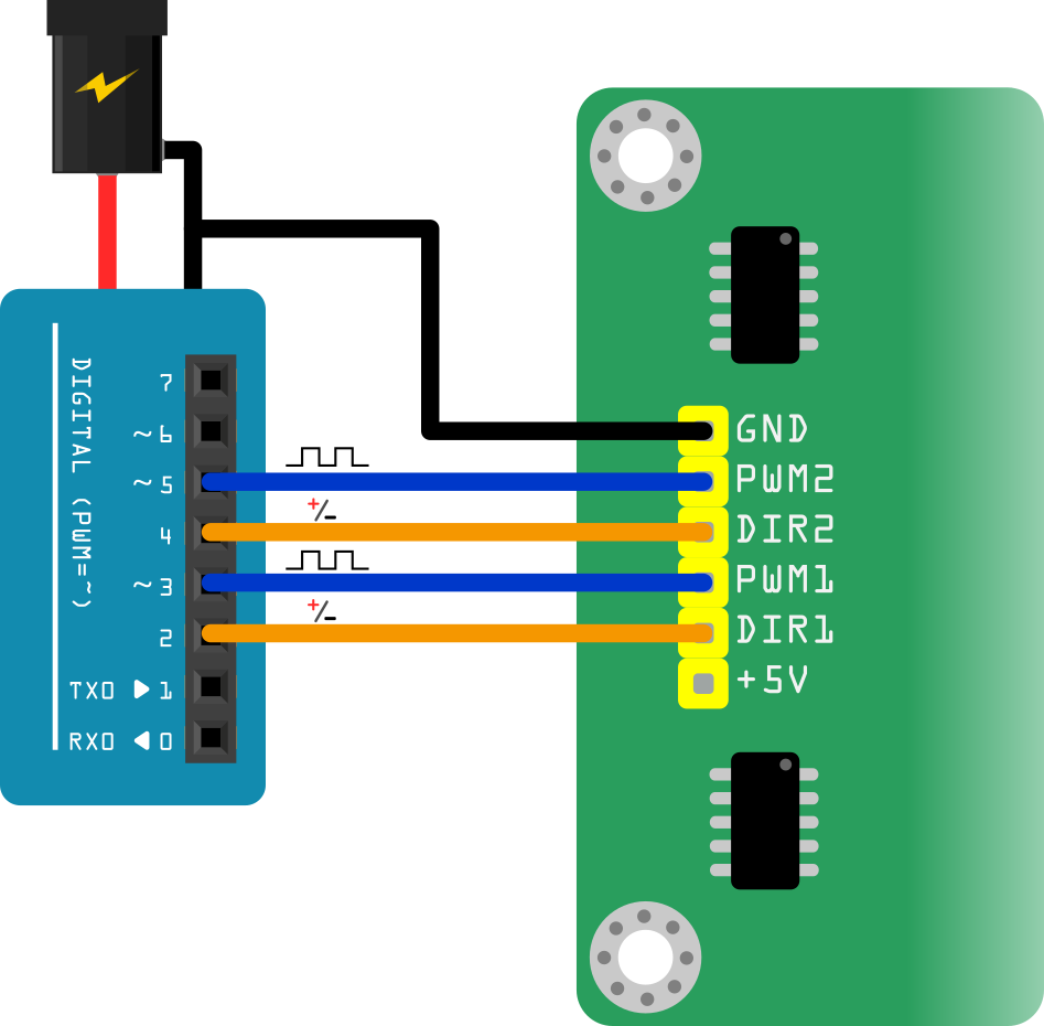 Fig.2
Fig.2
NB: The controller pins indicated are for representative purposes only, however pins: PWM1 AND PWM2 that are connected to pins enabled for the controller's PWM protocol (normally indicated on the board otherwise indicated in the data-sheet).
For the side with the connectors for the motors and the power supply, the connections are shown in the image below (Fig . 2). This card does not require a particular polarization for the connectors of the motors, being designed for DC motors (in direct current), if at the start of the application the motors turn in the opposite direction, it is sufficient to invert the connections of the motors to the tab.
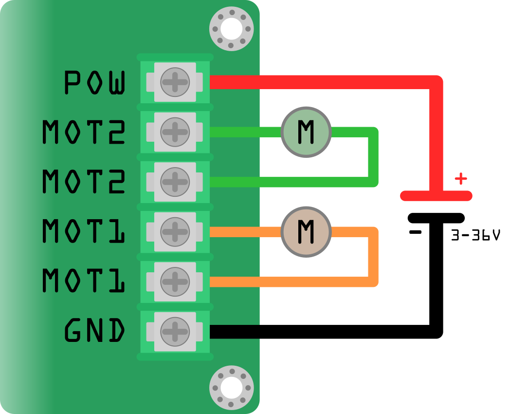 Fig. 3
NB: if you need reverse the connection of the motors make sure that each motor is connected to the respective terminal, otherwise you risk damaging the board.
The board is able to control the motors both in power and direction. The power control is carried out through the PWMx input, this protocol sends small pulsations of current to the motor, in this way it is possible to adjust the average power of the motor and consequently the speed. The direction control is instead carried out through the DIRx input, this pin can assume two states: high and low, depending on the state the motor will turn to the left or to the right.
PIN |
function |
| gnd (logical part) | This pin is connected to the gnd including that of the power supply, it connects to the gnd present on the controller |
| PWM1 | "Pulse With Modulation" input: a PWM signal on this pin corresponds to a PWM output on motor 1 output. |
| DIR1 | Motor 1 direction input, states: "HIGH" and "LOW" |
| PWM2 | "Pulse With Modulation" input: a PWM signal on this pin corresponds to a PWM output on motor 2 output. |
| DIR2 | Motor 2 direction input, states: "HIGH" and "LOW" |
| + 5V | This pin supplies a voltage of 5V with a maximum current of 500mA |
| MOT1 (X2) | These terminals are used to connect motor 1 to the board |
| MOT2 (X2) | These terminals are used to connect motor 2 to the board |
| PWO | The positive side of the power supply of the 3 - 36 V motors is connected to this terminal. |
| GND | The negative side of the power supply of the 3 - 36 V motors is connected to this terminal. This pin is also connected to the gnd present in the logic part of the board |
N.B .: The controller and the motor card must share a common ground.

 Total Rating